Basic Electronics for Beginners: What to Learn First
In this article (6 sections)
Electronics looks hard from the outside, but the base is small. A handful of ideas and a handful of circuits explain most of what you see inside a phone, a robot or an AC remote. This guide tells you what to learn, in what order, and which circuits to build with your own hands.
What to learn, in order
- Voltage, current and resistance, and Ohm’s law (V = I × R)
- Series and parallel connections, and how a voltage divider works
- Basic components: resistor, capacitor, diode, LED, transistor, switch, relay and simple sensors
- How to read a circuit diagram and its symbols
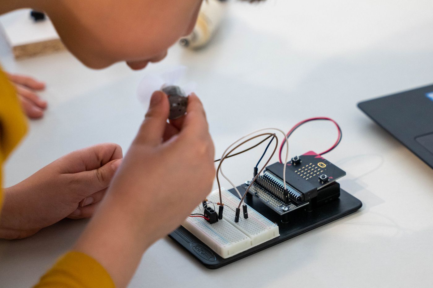
- How to use a breadboard and how its rows are connected
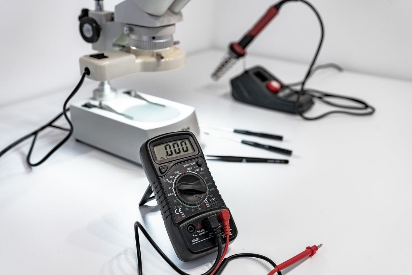
- How to use a multimeter to measure voltage, current and continuity
- A microcontroller such as Arduino or ESP32, and the basics of programming it
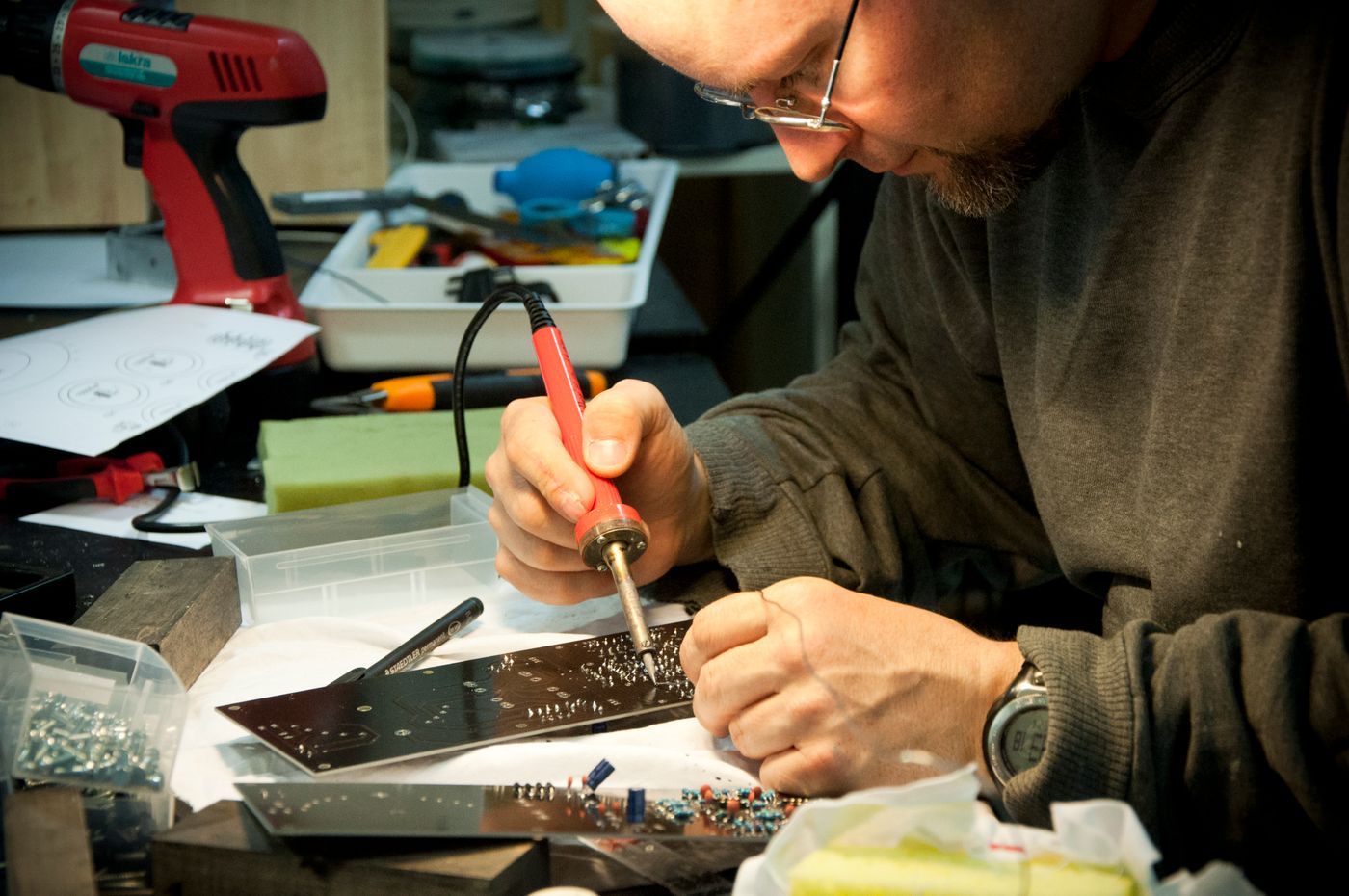
- Soldering, once your circuits work on the breadboard
- Testing and debugging: finding out why a circuit does not work
What you need to start
- A breadboard and a set of jumper wires
- An assorted pack of resistors, and a few LEDs and push buttons
- A multimeter
- An Arduino Uno and a USB cable
- A notebook, to draw each circuit and write what you observed
- A safe power source: a USB port or a small battery. Stay at low voltage and never connect your practice circuits to the mains supply
7 circuits to build first
Build these in order. Each one teaches one new idea, and each one makes the next easier. Do not just copy the circuit. Measure it with the multimeter and change a value to see what happens.
- Circuit 1LED with a resistorConnect an LED to a 5 V supply through a resistor. For a red LED that drops about 2 V and a safe current of about 15 mA, R = (5 − 2) ÷ 0.015 = 200 Ω, so use 220 Ω. You learn Ohm’s law and LED polarity.
- Circuit 2Push button and LEDMake a switch turn the LED on and off. You learn how a switch opens and closes the path of the current.
- Circuit 3Voltage dividerUse two equal resistors in series across 5 V and measure the middle point with the multimeter. You should read about 2.5 V. The formula is Vout = Vin × R2 ÷ (R1 + R2). This idea is used in almost every sensor circuit.
- Circuit 4Transistor as a switchUse an NPN transistor such as the BC547 with a resistor of about 1 kΩ at the base to switch an LED or a buzzer. Check the datasheet for the pin order. You learn how a small current controls a bigger one.
- Circuit 5Light sensorPut an LDR in a voltage divider and watch the voltage change as you cover it with your hand. You learn how sensors turn the real world into voltage.
- Circuit 6Arduino blink and buttonWrite the first program that blinks an LED, then read a button and print its state on the Serial Monitor. You learn how code controls hardware.
- Circuit 7Distance alarmConnect an HC-SR04 ultrasonic sensor and a buzzer to the Arduino so that the buzzer beeps faster as an object comes closer. You learn sensors, code and logic together.
A simple 4-week plan
- Week 1Learn voltage, current, resistance and Ohm’s law. Build circuits 1, 2 and 3.
- Week 2Learn components and the multimeter. Build circuits 4 and 5.
- Week 3Install the Arduino software and build circuit 6. Learn what each line of code does.
- Week 4Build circuit 7, then add one thing of your own, such as an LED that lights up when an object is near.
Common beginner mistakes
- Connecting an LED without a resistor
- Reversing the polarity of an LED, a capacitor or a battery
- A loose wire on the breadboard, or forgetting to connect the grounds together
- Connecting a higher voltage to a pin that expects 5 V or 3.3 V
- Not testing each part on its own before joining everything
- Copying a circuit without understanding it, so that you cannot fix it when it fails
How Robozz Lab helps you start
At Robozz Lab in Indore we teach exactly this path, hands-on and with one-to-one attention: basic electronics and circuits, components, controllers, programming, testing, tools, and then projects with IoT and ESP32. You build every circuit yourself with a trainer next to you, so a mistake becomes a lesson and not a roadblock. Many students come to us before their first internship or final-year project so that they start with a solid base.
Have a question? Message us on WhatsApp.
Talk to the Robozz Lab team directly about projects, school labs, training or internships.